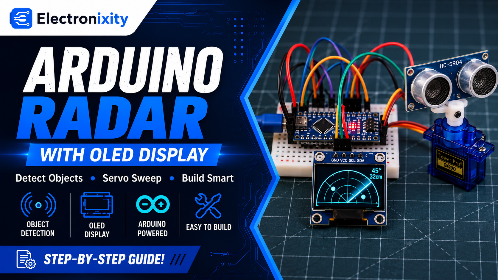
Arduino Radar Project with OLED Display — Step-by-Step Guide Leave a comment
Introduction
Have you ever wanted to build your own mini radar system using an Arduino? In this project, I’ll show you how to build an Arduino radar project using an ultrasonic sensor, a servo motor, and an OLED display.
The working principle is simple. A servo motor rotates the ultrasonic sensor from side to side while the Arduino measures the distance to nearby objects. The OLED display shows a radar-style scanning screen with the current angle, measured distance, and approximate position of detected objects.
This is a fun electronics project for beginners, STEM students, and robotics enthusiasts. It also helps you understand ultrasonic distance measurement, servo motor control, and graphical displays.
I’ve built and tested this project myself, and you can watch the demonstration below to see how it works.
YouTube Video: will be uploaded soon
Below, you’ll find the components list, wiring instructions, complete Arduino code, and troubleshooting tips to help you build your own radar system.
Components Required
You’ll need the following components to build this Arduino radar system.
| Component | Quantity | Purchase Link |
| Arduino Uno | 1 | Amazon.com – affiliate link |
| HC-SR04 ultrasonic sensor | 1 | Amazon.com – affiliate link |
| SG90 micro servo motor | 1 | Amazon.com – affiliate link |
| 0.96-inch SSD1306 I2C OLED display, 128 × 64 pixels | 1 | Amazon.com – affiliate link |
| Breadboard | 1 | Amazon.com – affiliate link |
| Male-to-male jumper wires | As needed | Amazon.com – affiliate link |
| USB cable compatible with Arduino Uno | 1 | Amazon.com – affiliate link |
| Regulated 5V power supply for the servo | 1, recommended | Amazon.com – affiliate link |
How the Main Components Work
Arduino Uno
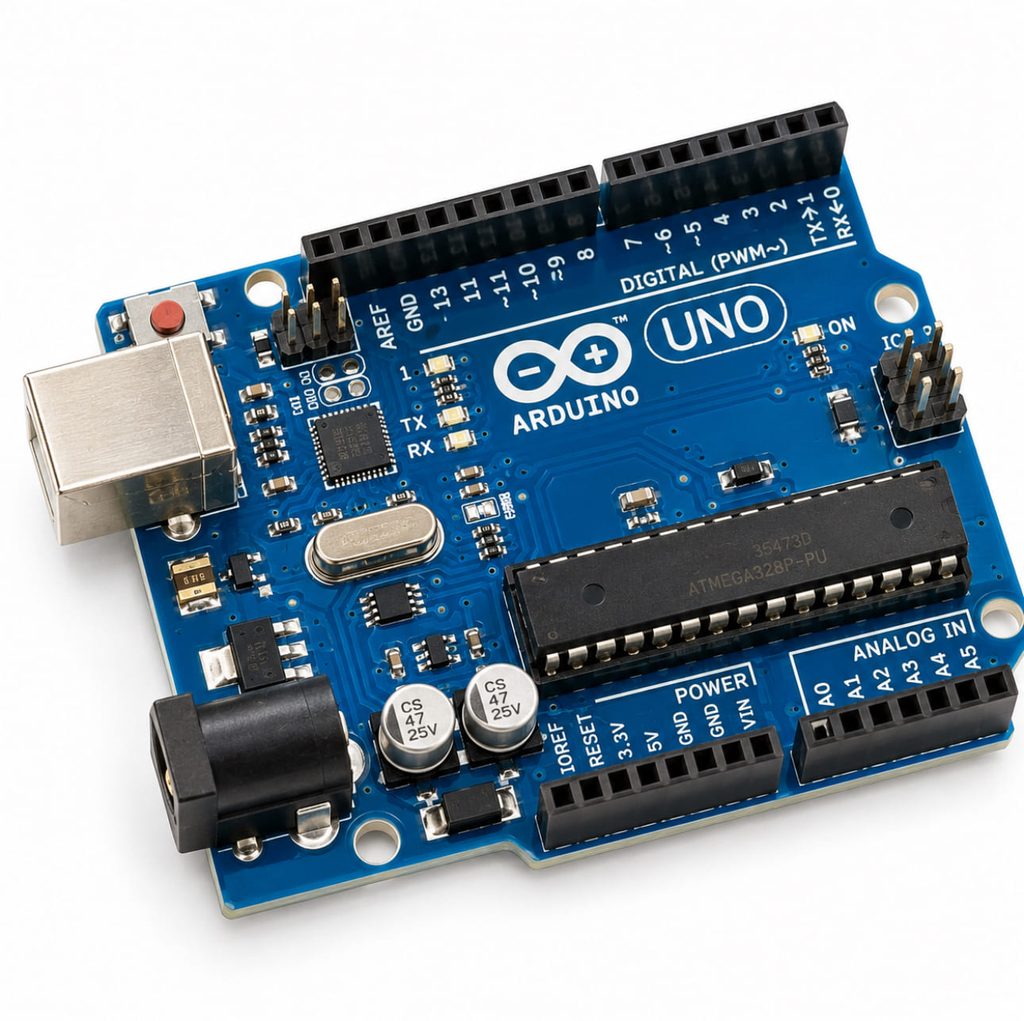
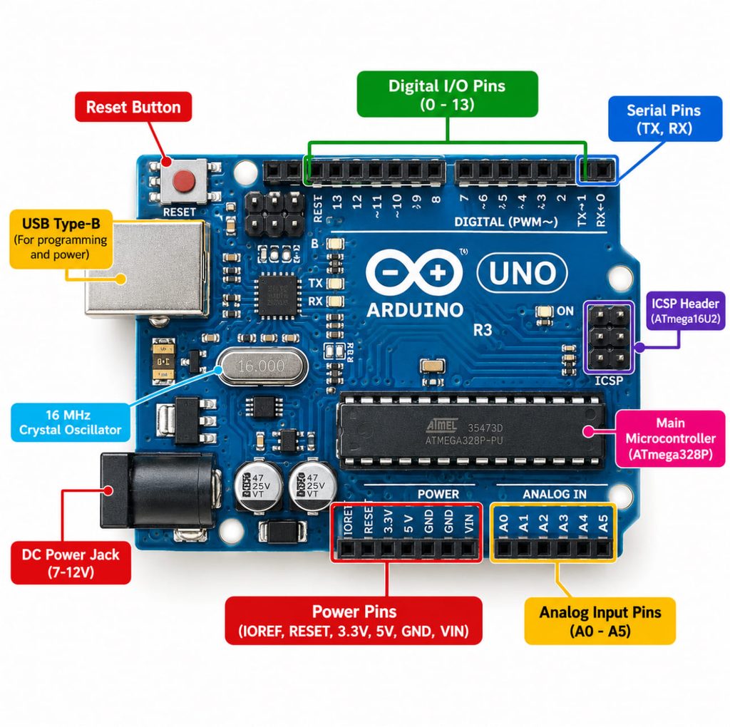
The Arduino Uno is the main controller of this project. It controls the servo motor, reads distance measurements from the ultrasonic sensor, calculates object positions, and updates the OLED display.
Key specifications:
- Microcontroller: ATmega328P on the classic Uno R3
- Operating voltage: 5V
- Digital I/O pins: 14
- Analog input pins: 6
- Clock speed: 16 MHz
HC-SR04 Ultrasonic Sensor
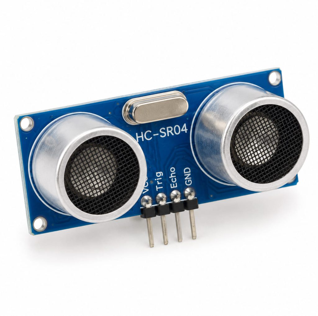
The HC-SR04 measures distance by transmitting ultrasonic sound waves and detecting their reflections from nearby objects.
The Arduino sends a trigger pulse to the sensor. The sensor then emits an ultrasonic burst and produces an echo pulse whose duration depends on how long the sound takes to travel to the object and return.
The distance is calculated using the following formula:
Distance (cm) = Echo duration in microseconds × 0.0343 ÷ 2
The division by two accounts for the sound’s round trip.
Typical HC-SR04 specifications:
- Operating voltage: 5V
- Commonly specified measuring range: approximately 2–400 cm
- Ultrasonic frequency: 40 kHz
- Trigger pulse: at least 10 microseconds
Actual detection range depends on the object’s size, surface, angle, and surrounding conditions.
SG90 Servo Motor
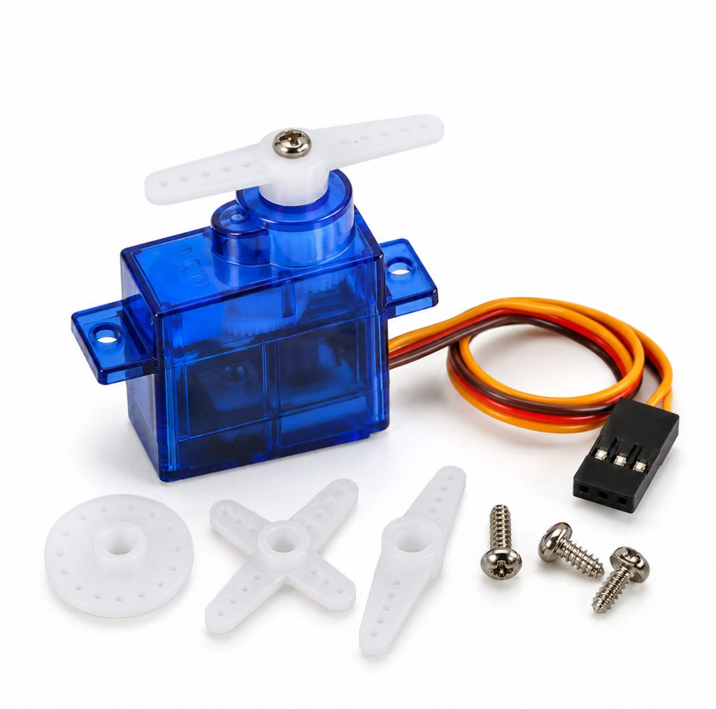
The SG90 servo motor rotates the ultrasonic sensor horizontally. The Arduino commands the servo to move to different angles, allowing the sensor to scan a wider area.
Typical specifications:
- Operating voltage: approximately 4.8–6V, depending on the model
- Movement range: approximately 180 degrees for many versions
- Control method: servo position pulses
The actual movement range depends on the servo model. Avoid forcing the shaft beyond its mechanical limits.
OLED Display
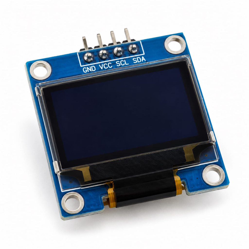
The OLED display provides a visual representation of the radar scan. It shows the current scanning angle, measured distance, radar arcs, and the approximate location of detected objects.
This project uses a 128 × 64-pixel SSD1306 I2C OLED display. Most modules use I2C address 0x3C, although some use 0x3D.
Wiring Connections
Before making connections, disconnect the Arduino from USB power.
HC-SR04 to Arduino Uno
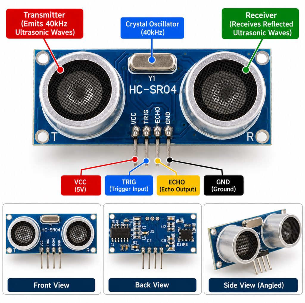
| HC-SR04 Pin | Arduino Uno Pin |
| VCC | 5V |
| GND | GND |
| TRIG | Digital pin 10 |
| ECHO | Digital pin 11 |
SG90 Servo Motor to Arduino Uno
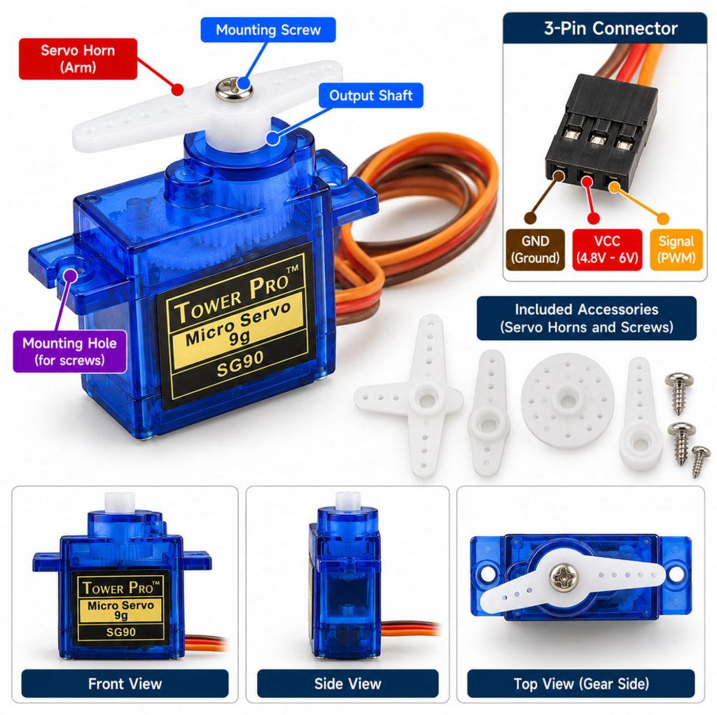
| Servo Wire | Connection |
| Red | Regulated 5V supply |
| Brown or black | GND |
| Orange, yellow, or white | Digital pin 9 |
Wire colors may vary, so check your servo’s documentation.
A servo can draw more current than the Arduino’s onboard 5V supply can comfortably provide. If the Arduino resets or the OLED flickers, use a suitable regulated 5V external supply for the servo. Connect the external supply’s ground to Arduino GND. Do not connect two independent 5V power outputs together.
OLED Display to Arduino Uno
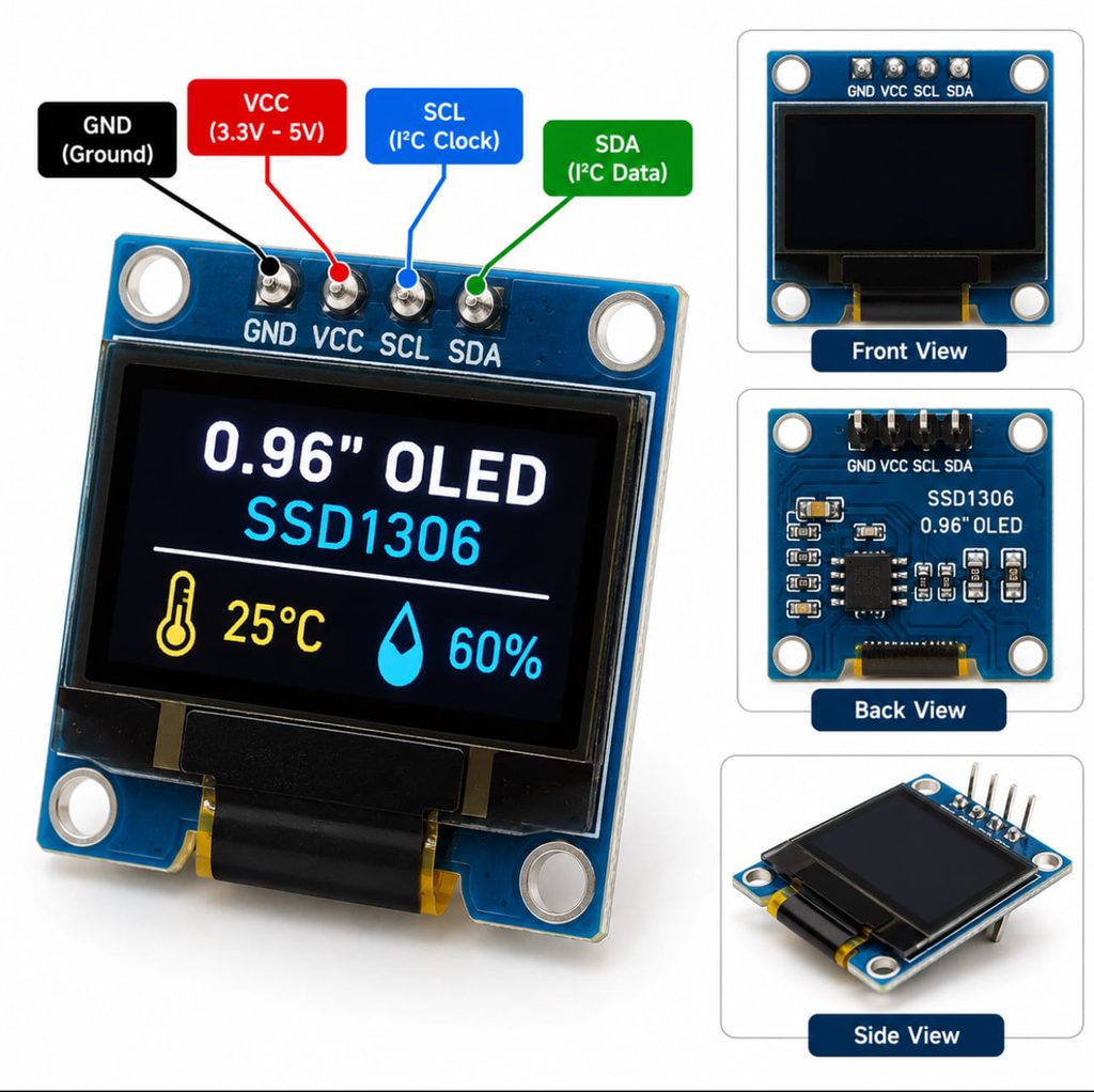
| OLED Pin | Arduino Uno R3 Pin |
| VCC | 5V, if supported by the module; otherwise use its specified voltage |
| GND | GND |
| SDA | A4 |
| SCL | A5 |
These SDA and SCL connections apply to the classic Arduino Uno R3.
Double-check the connections before powering on the circuit. Make sure the sensor can rotate freely without pulling on the wires.
Library Installation
This project requires the Servo, Adafruit GFX, and Adafruit SSD1306 libraries.
Step 1: Install Arduino IDE
Download and install the Arduino IDE from the official website:
https://www.arduino.cc/en/software
Connect your Arduino Uno to your computer using a USB cable.
Step 2: Install Adafruit SSD1306
- Open Arduino IDE.
- Go to Sketch > Include Library > Manage Libraries.
- Search for Adafruit SSD1306.
- Install the library by Adafruit.
Step 3: Install Adafruit GFX
Search for Adafruit GFX Library in Library Manager and install it.
Install any additional dependencies if prompted.
Step 4: Check the Servo Library
The Servo library is usually included with the Arduino IDE. If it is missing, search for Servo in Library Manager and install it.
Complete Arduino Radar Project Code
The following sketch is designed for an Arduino Uno, HC-SR04 ultrasonic sensor, SG90 servo motor, and SSD1306 I2C OLED display.
The servo scans from 0 to 180 degrees and then returns to the starting position. At each angle, the Arduino measures the distance and displays a radar-style visualization.
#include <Wire.h>
#include <Adafruit_GFX.h>
#include <Adafruit_SSD1306.h>
#include <Servo.h>

// -------------------- OLED CONFIG --------------------
#define SCREEN_WIDTH 128
#define SCREEN_HEIGHT 64
Adafruit_SSD1306 display(SCREEN_WIDTH, SCREEN_HEIGHT, &Wire, -1);   // -1 = no reset pin

// Radar origin (bottom center of screen)
const int ORIGIN_X = SCREEN_WIDTH / 2;
const int ORIGIN_Y = SCREEN_HEIGHT - 1;
const int RADAR_RADIUS = 60;      // max radius in pixels (should fit inside 64px height)

// -------------------- PINS --------------------
const int SERVO_PIN = 3;
const int TRIG_PIN  = 12;
const int ECHO_PIN  = 11;

// -------------------- SERVO CONFIG --------------------
const int MIN_ANGLE = 15;
const int MAX_ANGLE = 165;

Servo radarServo;
int servoAngle = MIN_ANGLE;   // starting angle
int servoStep  = 1;           // step per frame
bool sweepingForward = true;  // true: MIN_ANGLE -> MAX_ANGLE, false: back

// -------------------- ULTRASONIC CONFIG --------------------
const float MAX_DISTANCE_CM = 30.0; // anything farther is "no object"

// -------------------- FUNCTIONS --------------------

// Simple typing animation for a given text and total duration
void showTypingAnimation(const char* msg, uint16_t totalDurationMs)
{
  uint8_t len = strlen(msg);
  if (len == 0) return;

  // Calculate delay per character so full word takes ~totalDurationMs
  uint16_t perCharDelay = totalDurationMs / len;

  display.clearDisplay();
  display.setTextSize(1);
  display.setTextColor(WHITE);

  // Vertically center the text (roughly)
  uint8_t y = (SCREEN_HEIGHT - 8) / 2; // 8px font height
  display.setCursor((SCREEN_WIDTH - (len * 6)) / 2, y);
  // 6px per char (5px width + 1px space) for default font

  Serial.println(F("[SPLASH] Showing 'Alpha Electronz' typing animation"));

  for (uint8_t i = 0; i < len; i++) {
    display.print(msg[i]);
    display.display();
    delay(perCharDelay);
  }

  // small extra hold (optional)
  delay(300);
}

float readDistanceCm()
{
  // Trigger ultrasonic pulse
  digitalWrite(TRIG_PIN, LOW);
  delayMicroseconds(2);
  digitalWrite(TRIG_PIN, HIGH);
  delayMicroseconds(10);
  digitalWrite(TRIG_PIN, LOW);

  // Read echo time (timeout ~25ms => ~4m)
  long duration = pulseIn(ECHO_PIN, HIGH);

  if (duration == 0) {
    // No echo received in time
    Serial.println(F("[US] Timeout: no echo"));
    return -1;
  }

  // Convert time to distance (cm)
  float distance = duration / 58.0;  // HC-SR04 constant

  Serial.print(F("[US] duration="));
  Serial.print(duration);
  Serial.print(F(" us, distance="));
  Serial.print(distance);
  Serial.println(F(" cm"));

  return distance;
}

// Draw static radar circles and baseline
void drawRadarGrid()
{
  // Concentric circles
  display.drawCircle(ORIGIN_X, ORIGIN_Y, RADAR_RADIUS, WHITE);
  display.drawCircle(ORIGIN_X, ORIGIN_Y, RADAR_RADIUS * 2 / 3, WHITE);
  display.drawCircle(ORIGIN_X, ORIGIN_Y, RADAR_RADIUS / 3, WHITE);

  // Baseline (left-right)
  display.drawLine(ORIGIN_X - RADAR_RADIUS, ORIGIN_Y,
                   ORIGIN_X + RADAR_RADIUS, ORIGIN_Y, WHITE);
}

// Map servo angle to radar sweep angle (0..180° left->right)
float servoAngleToRad(int angle)
{
  // Clamp to valid range
  if (angle < MIN_ANGLE) angle = MIN_ANGLE;
  if (angle > MAX_ANGLE) angle = MAX_ANGLE;

  // Map servo angle (MIN_ANGLE..MAX_ANGLE) to display angle (0..180)
  // 0° -> right, 90° -> up, 180° -> left
  long displayDeg = map(angle, MIN_ANGLE, MAX_ANGLE, 0, 180);

  // NO extra inversion here – so sweep direction matches servo movement
  float rad = displayDeg * PI / 180.0;
  return rad;
}

void setup()
{
  Serial.begin(9600);
  Serial.println(F("\n=== Radar Setup Start ==="));

  pinMode(TRIG_PIN, OUTPUT);
  pinMode(ECHO_PIN, INPUT);

  radarServo.attach(SERVO_PIN);
  radarServo.write(servoAngle);
  Serial.print(F("[SERVO] Initial angle: "));
  Serial.println(servoAngle);
  delay(500);

  // OLED init
  if (!display.begin(SSD1306_SWITCHCAPVCC, 0x3C)) {
    Serial.println(F("[OLED] SSD1306 allocation failed!"));
    // If OLED init fails, stay here
    while (true) {
      pinMode(LED_BUILTIN, OUTPUT);
      digitalWrite(LED_BUILTIN, HIGH);
      delay(200);
      digitalWrite(LED_BUILTIN, LOW);
      delay(200);
    }
  }

  Serial.println(F("[OLED] SSD1306 initialized OK."));
  Serial.println(F("=== Radar Setup Done ==="));

  // --- Typing splash for "Alpha Electronz" ---
  showTypingAnimation("Alpha Electronz", 5000); // ~5 seconds total

  // Then show radar initializing and start normal project
  display.clearDisplay();
  display.setTextSize(1);
  display.setTextColor(WHITE);
  display.setCursor(0, 0);
  display.println(F("Radar Initializing..."));
  display.display();
  delay(1000);
}

void loop()
{
  // Move servo to current angle
  radarServo.write(servoAngle);
  Serial.print(F("[SERVO] Angle: "));
  Serial.println(servoAngle);
  delay(15);  // small delay for smooth motion

  // Read distance
  float distance = readDistanceCm();
  bool objectDetected = false;

  if (distance > 0 && distance <= MAX_DISTANCE_CM) {
    objectDetected = true;
    Serial.print(F("[OBJ] Detected at "));
    Serial.print(distance);
    Serial.println(F(" cm"));
  } else {
    Serial.println(F("[OBJ] No valid object in range"));
    distance = MAX_DISTANCE_CM; // clamp for drawing
  }

  // Prepare drawing
  display.clearDisplay();

  // Draw grid
  drawRadarGrid();

  // Calculate radar line angle
  float rad = servoAngleToRad(servoAngle);

  // End point of radar sweep line (max radius)
  int endX = ORIGIN_X + (int)(RADAR_RADIUS * cos(rad));
  int endY = ORIGIN_Y - (int)(RADAR_RADIUS * sin(rad)); // minus because screen Y grows downward

  // Draw sweeping line
  display.drawLine(ORIGIN_X, ORIGIN_Y, endX, endY, WHITE);

  // If object detected, draw a blip on the line
  if (objectDetected) {
    float normalized = distance / MAX_DISTANCE_CM;
    if (normalized > 1.0) normalized = 1.0;
    int rTarget = (int)(RADAR_RADIUS * normalized);

    int objX = ORIGIN_X + (int)(rTarget * cos(rad));
    int objY = ORIGIN_Y - (int)(rTarget * sin(rad));

    display.fillCircle(objX, objY, 2, WHITE);

    // Show text info
    display.setTextSize(1);
    display.setCursor(0, 0);
    display.print(F("OBJ: "));
    display.print((int)distance);
    display.println(F("cm"));

    display.setCursor(0, 10);
    display.print(F("Angle: "));
    display.print(servoAngle);
    display.println(F(" deg"));
  } else {
    display.setTextSize(1);
    display.setCursor(0, 0);
    display.println(F("No object"));
    display.setCursor(0, 10);
    display.print(F("Angle: "));
    display.print(servoAngle);
    display.println(F(" deg"));
  }

  display.display();

  // Update servo angle for next frame (back-and-forth sweep)
  if (sweepingForward) {
    servoAngle += servoStep;
    if (servoAngle >= MAX_ANGLE) {
      servoAngle = MAX_ANGLE;
      sweepingForward = false;
      Serial.println(F("[SERVO] Reached max, reversing sweep"));
    }
  } else {
    servoAngle -= servoStep;
    if (servoAngle <= MIN_ANGLE) {
      servoAngle = MIN_ANGLE;
      sweepingForward = true;
      Serial.println(F("[SERVO] Reached min, reversing sweep"));
    }
  }

  // Small delay to control sweep speed (tune as you like)
  delay(10);
}
Important: If your OLED uses I2C address 0x3D instead of 0x3C, change the OLED_ADDRESS definition. This sketch displays the current scan and measurement rather than keeping a history of previously detected objects
Testing the Project
After uploading the code, follow these steps.
- Connect the Arduino to your computer or a suitable power source.
- Confirm that the OLED displays the startup message.
- Check whether the servo rotates the sensor from side to side.
- Place a flat object approximately 30–50 cm in front of the sensor.
- Observe the OLED as the sensor scans toward the object.
- Move the object closer or farther away and observe how the displayed position changes.
Expected results:
- The servo continuously scans between 0 and 180 degrees.
- The OLED displays the current angle and measured distance.
- A target dot appears when an object is detected within the configured display range.
- The dot moves closer to or farther from the radar center as the measured distance changes.
Keep in mind that the sensor measures one direction at a time, so the object marker updates as the servo reaches the object’s direction.
Troubleshooting
Problem 1: OLED Display Is Blank
Possible causes: Incorrect I2C address, reversed SDA/SCL connections, incorrect power, or an incompatible display controller.
Solution: Check the wiring and confirm the OLED uses the SSD1306 controller. Try address 0x3D if 0x3C does not work. An I2C scanner sketch can help identify the correct address.
Problem 2: Servo Motor Does Not Rotate
Possible causes: Incorrect signal pin, insufficient current, loose wiring, or missing common ground.
Solution: Verify that the signal wire connects to digital pin 9. Check the servo power supply and connect the external supply’s ground to Arduino GND. Test the servo separately if necessary.
Problem 3: Incorrect Distance Readings
Possible causes: Poor target angle, soft surfaces, excessive distance, or sensor movement during measurement.
Solution: Test with a large, flat object placed directly in front of the sensor. Increase the servo settling delay if necessary and check the sensor connections.
Problem 4: Radar Dots Appear in the Wrong Direction
Possible causes: Incorrect sensor mounting or a different servo orientation.
Solution: Check which physical direction corresponds to 0 and 180 degrees. Adjust the angle mapping if the displayed radar is mirrored.
Problem 5: Arduino Resets or OLED Flickers
Possible causes: Insufficient power for the servo or loose connections.
Solution: Use a regulated 5V supply with sufficient current for the servo and connect its ground to Arduino GND. Avoid overloading the Arduino’s onboard 5V supply.
Ideas to Expand the Project
Once your basic radar is working, you can add more features.
- PC Radar Visualization: Send the angle and distance readings to a computer and create a more detailed radar interface using Python and Pygame.
- Buzzer Alert: Add a buzzer to sound when an object is detected within a specified distance.
- Obstacle-Avoidance Robot: Mount the sensor on a mobile robot and use the measurements to help the robot navigate around obstacles.
- Persistent Target Tracking: Store previous measurements and redraw detected objects across multiple frames to create a radar trail.
- Wireless Monitoring: Add an ESP32 or another wireless module to transmit measurements to a computer or mobile dashboard.
These upgrades can help you learn more about robotics, embedded programming, and sensor integration.
Frequently Asked Questions
How do you make an Arduino radar using an ultrasonic sensor?
Connect an HC-SR04 ultrasonic sensor to an Arduino, mount it on a servo motor, and program the Arduino to scan different angles while measuring distance. An OLED display can show the scan direction and approximate object positions.
Can I make an Arduino radar without an OLED display?
Yes. You can send angle and distance measurements to the Serial Monitor or a computer-based visualization. An OLED is useful if you want a standalone radar display.
What is the maximum range of an Arduino ultrasonic radar?
The HC-SR04 is commonly specified for approximately 2–400 cm under suitable conditions. Actual performance varies with the target and environment. This tutorial uses a 200 cm display range.
Why is a servo motor used in an Arduino radar project?
The servo rotates the ultrasonic sensor so it can measure distances in multiple directions. Without the servo, the sensor generally measures objects within its fixed detection area.
Is an Arduino ultrasonic radar the same as a real radar system?
No. This project uses ultrasonic sound waves rather than radio waves. It recreates the scanning and visualization concept of radar for educational purposes, but it is not a true radio radar system.
Conclusion
This Arduino radar project is a great way to explore ultrasonic distance measurement, servo motor control, and OLED graphics using affordable electronics components.
With an Arduino Uno, an HC-SR04 ultrasonic sensor, an SG90 servo motor, and a small OLED display, you can build a working radar-style scanning system and learn how the different components communicate.
Start with the basic circuit, test the code, and experiment with different distances and angles. Once everything works, you can add a buzzer, a computer visualization, wireless monitoring, or persistent target tracking.
Watch the project demonstration on YouTube to see the radar in action. If you found this tutorial useful, please like the video, subscribe to the channel, and leave a comment with your questions or suggestions for future Arduino projects.
